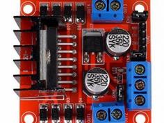
This L293D driver module is a medium power motor driver perfect for driving DC Motors and Stepper Motors. It uses the popular L293D motor driver IC. It can drive 4 DC motors in one direction, or drive 2 DC motors in both the directions. This motor driver is perfect for robotics and mechatronics projects for controlling motors from microcontroller, switches, relays, etc. Perfect for driving DC and Stepper motors for micromouse, line following robots, robot arms, etc. Product Images are shown for illustrative purposes only and may differ from actual product.

Thumb

0 repins 0 comments

Getting an original TowerPro mini Servo Motor is not an economical option at all!!! And is also a very difficult task to recognize and buy an original TowerPro mini servo motor, Because there are many suppliers spread over different online shops who are selling fake mini servo motors under this Brand name. believes in satisfied customers, so whatever the product is we first import them then test them for their supplier defined and standard capabilities. Only after doing all the possible quality checks, we make the product available to our customers. It equips Carbon Fiber Gears which makes the servo motor much lighter than the same metal gear motor. For small load applications using the metal gear, servo motor adds on unnecessary weight, so we suggest using these lightweight plastic gear servo motors. The TowerPro SG90 9g Mini Servo is a 180° rotation servo. It is a Digital Servo Motor that receives and processes PWM signal faster and better. It equips sophisticated internal circuitry that provides good torque, holding power, and faster updates in response to external forces. Wire Description RED – Positive Brown – Negative Orange – Signal Mini Servo Motors and Accessories Features: High resolution Accurate positioning Fast control response Constant torque throughout the servo travel range Excellent holding power

Thumb

0 repins 0 comments

Lm393 LDR Sensor Module The LM393 LDR Sensor Module utilizes a superior LM393 voltage comparator. It can be easily installed and features a sensitive photosensitive resistance sensor, providing a clean and precise waveform for the comparator output signal. The adjustable potentiometer allows for a driving ability of 15mA and can regulate the brightness of the detected light. This module operates within a working voltage range of 3.3V to 5V, producing a digital switch output. Its sensitivity to light makes it suitable for detecting ambient brightness and intensity. In the absence of light or sufficient intensity, the DO output will be at a high level. On the other hand, if the light surpasses this value, the DO output will be low. The digital DO output can easily connect to a microcontroller which can then detect whether it is at a high or low level, allowing for detection of changes in environmental light. This board’s digital output DO port allows for direct connection with our relay modules, which are currently on sale in our store. Additionally, it can serve as a photoelectric switch. The analog output AO can be connected to an AD module for more accurate measurement of light intensity via the converter. The Pin on the Interface: The VCC is our power supply. Ground, or GND for short. The signal output in digital form. The signal output is in analog form. Powerful illumination, LED lighting, emitting a lower intensity. Dim illumination, LED disabled, elevated output signal. Adjustable is the sensitivity. Characteristics of Lm393 LDR Sensor Module: Included in the package are screws for mounting. Simple to set up Indicator light for signal output. The 4 PIN LDR module. Capable of sensing changes in surrounding light levels and adjusting sensitivity with the use of a blue digital potentiometer. The digital switch output (0 and 1) is compatible with Arduino, Raspberry, and other microcontroller boards. It also has an analog voltage output (AO).

Thumb

0 repins 0 comments

L298N Motor Driver Module 2A This L298N Motor Driver Module is a high power motor driver perfect for driving DC Motors and Stepper Motors. It uses the popular L298N motor driver IC and has the onboard 5V regulator which it can supply to an external circuit. It can control up to 4 DC motors, or 2 DC motors with directional and speed control This motor driver is perfect for robotics and mechatronics projects and perfect for controlling motors from microcontrollers, switches, relays, etc. Perfect for driving DC and Stepper motors for micro mouse, line-following robots, robot arms, etc. Note: It is recommended to buy a good quality version of this product. You can buy it by clicking here: L298N Motor Driver Module – Good Quality. The reason is that the good quality version product has a better quality of components as compared to standard ones. Pins: Out1:Motor A lead out Out2:Motor A lead out Out3:Motor B lead out Out4:Mo (Can actually be from 5v-35v, just marked as 12v) GND :Ground 5v :5v input (unnecessary if your power source is 7v-35v, if the power source is 7v-35v then it can act as a 5v out) EnA :Enables PWM signal for Motor A (Please see the “Arduino Sketch Considerations” section) In1 :Enable Motor A In2 :Enable Motor A In3 :Enable Motor B In4 :Enable Motor B EnB :Enables PWM signal for Motor B (Please see the “Arduino Sketch Considerations” section) Usage: H-bridges are typically used in controlling motors speed and direction but can be used for other projects such as driving the brightness of certain lighting projects such as high powered LED arrays. Two things to mention: Make sure you have all of your grounds tied together; Arduino, Power source, and the Motor Controller. The PWM Pins are unnecessary if you do not want to control PWM features. Arduino Sketch Considerations: The Arduino code sketch is pretty straightforward. Since there isn’t a library for the L298N Dual H-Bridge Motor Controller you just have to declare which pins the controller is hooked to. The “int dir(number)Pin(letter) pins can be connected to any available digital pin you have available, as long as you declare the correct pin in your sketch. This makes the L298N Dual H-Bridge Motor Controller very versatile if your project is using a lot of Arduino pins. The int“speeding(letter)” pins need to be connected to a PWM pin on the Arduino if you want to enable speed control through PWM. As a quick cheat I have included a list of PWM pins for the main two types of Arduino I use: AT MEGA PWM: 2 to 13 and 44 to 46. Provide 8-bit PWM output with the analogWrite() function. UNO PWM: 3, 5, 6, 9, 10, and 11. Provide 8-bit PWM output with the analogWrite() function. Note: Built-in 5v power supply, when the driving voltage is 7v-35v Features: -Current Sense for each motor. -Heatsink for better performance. -Power-On LED indicator. -Drives up to 4 motors.

Thumb

0 repins 0 comments

Find the best cost on Piezo Electric Buzzer in India. Shop now at Ainow for low prices on high-quality products for your electronics project

Thumb

0 repins 0 comments

Find the best cost on 7X2 cm wheel white in India. Shop now at Ainow for low prices on high-quality products for your electronics project

Thumb

0 repins 0 comments

L Clamp Bracket This motor mounting bracket is designed for Center Shaft Gear Motor to make the motor mounting easier and faster. The clamps serve as the fundamental parts when it comes to chassis. With this Center Shaft Gear Motor L Clamp Bracket motor mounting will become very convenient. This L Clamp bracket for Johnson Gear Motor is made up of 2mm thick Mild Steel which gives them excellent strength and stability. It has 13.5mm diameter holes for attaching the motor to the bracket and also 3mm diameter holes for mounting the bracket to the chassis or application. The L Clamp bracket is compatible with our Center Shaft DC Geared Motor. Note:We haven’t included any Center Shaft DC Geared Motor in this pack, buy them separately at Robu.in online shop Applications: DC motor position/velocity control Position and velocity servomechanisms Factory automation robots Numerically controlled machinery Computer printers and plotters Motor mounting side Height: 40 mm Width: 40 mm Bracket mounting side Length: 40 mm Width: 24 mm Features: Good Quality mounting brackets. Made up of good quality MS. Specially designed for Center Shaft Gear Motor. Possess good stability and durability.

Thumb

0 repins 0 comments

Find the best cost on power supply adapter in India. Shop now at Ainow for low prices on high-quality products for your electronics project

Thumb

0 repins 0 comments

POWER SUPPLY BOARD: ABOUT THE PRODUCT Power Board WHAT WE ARE GOING TO DO: -It is a general purpose board to provide power supply. HARDWARE AND SOFTWARE REQUIRED: Hardware: 12V Adaptor-1 Nos Power board-1 Nos. Multimeter-1 Nos DETAIL AND OPERATION OF THE PRODUCT : Provide 12v power supply board It has three various power supply pins It has 7805 voltage regulator is present to convert 12v to 5v It has 1117 voltage regulator is present to convert 5v to 3.3v It has two LED RED & YELLOW. RED led is used to indicate the 5v power supply YELLOW led is used to indicate the 3.3v power supply CONNECTION: -Provide 12v power supply to power board PROCEDURE: As per connections given Place the multimeter positive to the 12v and the gnd of multimeter to the gnd pin Same should be followed for the 5v and 3.3v OUTPUT : The corresponding values can be displayed in the multimeter.. WHAT SHOULD NOT BE DONE: Connection of vcc & gnd should not change.

Thumb

0 repins 0 comments

1602 LCD Display Module In order to incorporate visual output into your Arduino projects, a display is necessary. If minimal display is required, the1602 LCD Display offers a suitable solution. Introducing the 16*02 LCD Display – an affordable and effortless way to incorporate a 16×2 Black on RGB Liquid Crystal Display into your project. Featuring a 16 character by 2 line display with sharp black text against a vibrant yellow background and backlight. This fabulous yellow backlight LCD display is perfect for Arduino-based projects. The 1602 LCD Display boasts a striking yellow backlight and can be easily linked with an Arduino or other microcontrollers. The display can present either straightforward text or numerical data collected by the sensors, such as temperature or pressure. It may also reveal the number of cycles executed by the Arduino. One factor to keep in mind is the consumption of 8 Arduino pins for the display to function properly. Fortunately, there is an available I2C adapter that can be directly soldered onto the display’s pins. This means that you only need to connect the I2C pins, which requires a reliable library and minimal coding effort. We also offer a version of the LCD module with a pre-installed I2C adapter – click on the name below to view it. The 1602 LCD Display features an IIC/I2C interface for easy connectivity. To access additional displays, simply click below. The LED/LCD display is one of the key features of this product, offering a clear and vibrant readout. Included in the package are various attributes for your convenience. The display is 16 characters wide with 2 rows. Text in black against a vibrant yellow backdrop. The lone LED backlight can be easily dimmed using either a resistor or PWM. Easily manageable with 6 digital lines, making any analog or digital pins suitable for control.

Thumb

0 repins 0 comments

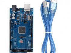
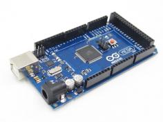
ARDUINO MEGA 2560 Arduino mega 2560 Atmega2560-16au compatible with Arduino is a micro-controller board based on the ATmega2560 IC. It has a USB host interface for connecting to Android phones through the MAX3421e IC. The MEGA ADK is equipped with versatile components, including 54 digital input/output pins (15 of which can also function as PWM outputs), 16 analog inputs, 4 UARTs (hardware serial ports), a 16 MHz crystal oscillator, a USB connection, a power jack, an ICSP header, and a reset button. This board is based on the Mega 2560 design and shares similar features with the Mega 2560 and Uno. Additionally, it has an ATmega8U2 programmed as a USB-to-serial converter. In its third revision, the Mega ADK includes a resistor that pulls the 8U2 HWB line to ground for easier access to DFU (Device Firmware Upgrade) mode. New features on the board include: As a result of the -1.0 pin-out, the SDA and SCL pins are near the AREF pin, and two additional pins are placed near the RESET pin, the IOREF, which allows the shields to adjust to the board’s voltage. AVR boards, which operate at 5V, and Arduino Due boards, which operate at 3.3V, will both be compatible with shields in the future. The second pin is unconnected, and is reserved for future purposes. Circuits with a stronger RESET function. An external power supply or USB connection can be used to power the arduino mega 2560 R3 Android Accessory Development Kit (ADK). Power is selected automatically. External (non-USB) power can come from either an AC-to-DC adapter (wall-wart) or battery. An adapter can be connected by plugging a 2.1mm center-positive plug into the board’s power socket. -Leads from a battery can be inserted in the GND and Vin pin headers of the POWER connector. Since the Mega R3 Android Accessory Development Kit (ADK) is a USB host, the phone will attempt to draw power from it when charging. When the ADK is power over USB, 500mA is available for the phone and board. Features and specifications: Arduino Mega 2560: Atmel is the programmer Microcontroller ATmega2560. There are 54 digital input/output terminals (14 of which have programmable PWM outputs). There are 16 analog inputs. There are four UARTs (hardware serial ports). A crystal clock with a frequency of -16 MHz. -Bootloader that allows sketches to be downloaded via USB without having to go through other writers. The device can be powered via USB or via an external power supply (not supplied). A heavy gold plate construction is used. 16 MHz clock speed. The bootloader uses 8 KB of the 256 KB flash memory. -Operating voltage: 6 ~ 12 volts. Arduino mega 2560 cable: Pluggable on the hot side. -Compatible with PCs. Strain relief and PVC overmolding ensure error-free data transmission for a lifetime. An aluminum under-mold shield helps meet FCC requirements for KMI/RFI interference. In addition, foil and braid shields comply with fully rated cable specifications, reducing EMI/FRI interference. High-Performance Error-Free Transmission. Case made of transparent acrylic: ARDUINO MEGA 2560 R3 (unassembled) compatible. It is possible to adjust the cover. Transparent color. Acrylic is the material used. The power of follows: What follows is: The Arduino board’s input voltage when it’s powered by an external source (rather than 5 volts from the USB connection or another regulated power source). If you are using the power jack to supply voltage, you can access it through this pin. In this pin, a regulated 5V is output from the board’s regulator. The board can be powered by the DC power jack (7 – 12V), the USB connector (5V), or the VIN pin (7-12V). It is not recommended to supply voltage to your board via the 5V or 3.3V pins, as it bypasses the regulator and can damage it. The onboard regulator generates a 3.3 volt supply with a maximum current draw of 50 milliamps. The ground pin is GND. This pin on the Arduino board serves as the voltage reference for the microcontroller. A properly configured shield can read the IOREF pin voltage and select the appropriate power source or enable voltage translators on the outputs for working with 5V or 3.3V. The memory In the arduino Mega 2560 R3 Android Accessory Development Kit (ADK), there is 256 KB of flash memory for storing code (of which 8 KB is used for the bootloader); 8 KB of SRAM, and 4 KB of EEPROM (which can be read and written). The inputs and outputs With pinMode(), digitalWrite(), and digitalRead() functions, the arduino Mega 2560 R3 Android Accessory Development Kit (ADK)’s 50 digital pins can be used as inputs and outputs. Each pin is powered by 5 volts and can provide or receive a maximum current of 40 milliamps. There is an internal pull-up resistor (20-50 kOhm) that is disconnected by default. Additionally, some pins have specialized functions: It can receive (RX) and transmit (TX) TTL serial data. Pins 0 and 1 are also connected to the corresponding pins of the ATmega8U2 USB-to-TTL Serial chip. The external interrupts are 2 (interrupt 0), 3 (interrupt 1), 18 (interrupt 5), 19 (interrupt 4), 20 (interrupt 3), and 21 (interrupt 21). The attachInterrupt() function can be used to trigger interrupts on low values, rising or falling edges, or changes in values. The analogWrite() function provides 8-bit PWM output from 2 to 13 and 44 to 46. There are four SPI pins on the ICSP header, which are physically compatible with the Uno, Duemilanove, and Diecimila: 50 (MISO), 51 (MOSI), 52 (SCK), 53 (SS). MAX3421E is the USB host. Maxim X3421E It uses the SPI bus to communicate with Arduino. It uses the following pins: Seven (RST), fifty (MISO), fifty-one (MOSI), and fifty-two (SCK). Please do not use Digital pin 7 as an input or output because it is used for MAX3421E communication PJ3 (GP_MAX), PJ6 (INT_MAX), PH7 (SS) are not broken out on headers. A built-in LED is connected to digital pin 13. When the pin is HIGH, the LED is on, when it is LOW, it is off. Wire library supports TWI communication using pins 20 (SDA) and 21 (SCL). These pins are not located in the same place as the TWI pins on the Duemilanove or Diecimila boards. Inputs in the Mega R3 Android Accessory Development Kit (ADK) have a resolution of 10 bits each (i.e. 1024 different values). In default, they measure from ground to 5 volts, but you can adjust the upper end of their range by using the AREF pin and analogReference() function. There are a few other pins on the board as well: A reference voltage for analog inputs. Use with analogReference. Typically used to add a reset button to shields that block the board’s reset button. Bring this line LOW to reset the microcontroller. The communication process The Arduino Mega 2560 R3 Android Accessory Development Kit (ADK) offers various options for communicating with different devices. With the ATmega2560, there are four hardware UARTs available for TTL (5V) serial communication. Additionally, an ATmega8U2 on the board allows one of the UARTs to be used for USB communication and creates a virtual com port for software on the computer. While Windows machines may require a .inf file, OSX and Linux machines will automatically detect the board as a COM port. The Arduino software features a convenient serial monitor that enables straightforward exchange of textual data between the board and other devices. The board’s RX and TX LEDs will blink to indicate data transmission through the ATmega8U2/16U2 chip and USB connection to the computer (note: not for serial communication on pins 0 and 1). Additionally, serial communication can be achieved on any of the MEGA ADK’s digital pins with the help of a Software-serial library. The ATmega2560 also supports TWI and SPI communication. To make use of the TWI bus, refer to the included Wire library in the Arduino software. For SPI communication, utilize the SPI library. Any device that has a USB port can connect and interact with the Arduino MEGA 2560 ADK thanks to the USB host interface provided by the MAX3421E IC. You can use it to control Canon cameras, interact with keyboard, mouse, and game controllers such as the Wiimote and PS3 for example, as well as interact with many types of phones. The programming language The Mega R3 Android Accessory Development Kit (ADK) can be used with the Arduino software (download). For details, check out the reference and tutorials. The ATmega2560 on the MEGA ADK comes preburned with a boot-loader (the same on Mega 2560) that allows you to upload new code without using an external hardware programmer. In order to communicate with it, it uses the STK500v2 protocol (reference, C header files). See these instructions for details on bypassing the bootloader and programming the microcontroller using Arduino ISP or similar. Source code for the ATmega8U2 firmware can be found in the Arduino repository. The ATmega8U2 is loaded with a DFU bootloader, which can be activated by: Boards with Rev1: Resetting the 8U2 requires connecting the solder jumper on the back of the board (near the map of Italy). It is easier to put the 8U2/16U2 HWB line into DFU mode on Rev2 or later boards since a resistor pulls the line to ground. To load a new firmware, you can use Atmel’s FLIP software (Windows) or the DFU programmer (Mac OS X and Linux). For more information, see this user-contributed tutorial. If you use the ISP header and an external programmer, you can overwrite the DFU bootloader. Reset (automatic) software Instead of physically pressing the reset button, the Arduino MEGA ADK has the ability to be reset through a connected computer. This is achieved by connecting one of the hardware flow control lines (DTR) of the ATmega8U2 to the reset line of the ATmega2560 using a 100 nano-farad capacitor. By asserting this line (taking it low), the reset line briefly drops and resets the chip. The Arduino software utilizes this feature, allowing you to easily upload code by pressing a button in the environment. This allows for a shorter timeout on the boot-loader, as the lowering of DTR can be easily synchronized with the beginning of the upload process. As a result, when the MEGA ADK is connected to a Mac OS X or Linux computer, it automatically resets and enters bootloader mode for a brief moment. During this time, if any data besides new code is sent to the board, it will be ignored as per its programming. However, it will intercept and process the first few bytes of data received after establishing a connection. When a sketch on the board receives initial configuration or data upon startup, ensure that the corresponding software waits for a brief moment before transmitting this information. The MEGA ADK has a trace that can be deactivated to disable the auto-reset function. The two pads on either side of the trace can be soldered together to reactivate it. This is labeled as “RESET-EN”. Alternatively, you can potentially disable the auto-reset by connecting a 110-ohm resistor from 5V to the reset line; refer to this forum thread for further instructions. Overcurrent protection for USB devices Using the arduino Mega 2560 R3 Android Accessory Development Kit (ADK), you can protect your computer’s USB ports from shorts and overcurrents with a resettable polyfuse. In spite of the fact that most computers have their own internal protection, the fuse provides another layer of security. In the event that a short or overload occurs, the fuse will automatically shut down the USB connection. Shield compatibility and physical characteristics The Arduino mega 2560 R3 Android Accessory Development Kit (ADK) PCB has a maximum length of 4 inches and a width of 2.1 inches. The USB connector and power jack extend beyond the length measurement. The board can be attached to a surface or case using three screw holes. Keep in mind that the distance between digital pins 7 and 8 is 160 mil (0.16″), which is not an even multiple of the standard 100 mil spacing of the other pins. Additionally, the MEGA ADK is designed to be compatible with most shields made for the Uno, Diecimila, or Duemilanove boards. All digital pins 0 to 13 (as well as the adjacent AREF and GND pins), the power header, and the ICSP header, are in the same location. Moreover, the main UART (serial port) is located on the same pins (0 and 1); and external interrupts 0 and 1 (pins 2 and 3 respectively). SPI is also available through the ICSP header on the MEGA ADK and Duemilanove / Diecimila. It is important to note that I2C is not located on the same pins as DMA on the MEGA ADK (20 and 21);

Thumb

0 repins 0 comments

Arduino Atmega 2560 R3 Microcontroller Board With the MAX3421e IC, the Mega 2560 Atmega2560-16au compatible with Arduino is a microcontroller board based on the Arduino Atmega 2560 R3. With a total of 54 digital input/output pins (including 15 PWM outputs), 16 analog inputs, and 4 UARTs, the MEGA ADK is jam-packed with features. It also boasts a 16 MHz crystal oscillator and comes equipped with a USB connection, power jack, ICSP header, and reset button. Based on the Arduino Atmega 2560 r3, this board shares many similarities with its counterparts, including the ATmega8U2 program that serves as a USB-to-serial converter. In fact, the Mega ADK revision 3 even includes a resistor that conveniently pulls the 8U2 HWB line to ground for easier DFU(Device Firmware Upgrade) mode access. New features on the board include: As part of the 1.0 pin-out, the shields will be able to adjust to the voltage provided by the board by adding SDA and SCL pins near the AREF pin and two new pins near the RESET pin, the IOREF. Shields in the future will be compatible with boards that use AVR, which operate at 5V, and Arduino Due, which operates at 3.3V. The second pin, which is not connected, will be used for future purposes. Circuit with a stronger RESET. A USB connection or an external power supply can be used to power the Arduino Atmega 2560 R3 Android Accessory Development Kit (ADK). An AC-to-DC adapter (wall-wart) or battery can be used to supply external (non-USB) power. An adapter can be connected by plugging a 2.1mm center-positive plug into the board’s power jack. GND and Vin pin headers on the POWER connector can be inserted with battery leads. Since the Mega R3 Android Accessory Development Kit (ADK) is a USB Host, the phone will attempt to draw power from it when it needs to charge. When the ADK is powered over USB, 500mA is available for the phone and board. Features and specifications: Arduino Atmega 2560 r3 : Atmel is the programmer Microcontroller ATmega2560. A total of 54 digital input/output terminals (14 of which have programmable PWM outputs) are available. There are 16 analog inputs. There are four UARTs (hardware serial ports). A crystal clock with a frequency of -16 MHz. A bootloader allows sketches to be downloaded via USB without having to go through an external writer. -Powered by USB or external power supply (not supplied). The device will automatically switch between power sources. A heavy gold plate construction is used. The clock speed is 16 MHZ. Bootloader uses 8 KB of the 256 KB flash memory. The operating voltage is 6 x 12 volts. Mega 2560 Arduino cable: It is hot pluggable. -Compatible with PCs. Strain relief and PVC overmolding ensure error-free data transmissions for a lifetime. -Aluminum under-mold shield helps meet FCC requirements for KMI/RFI interference. -Filled and braided shield conforms to fully rated cable specifications and reduces EMI/FRI interference. Error-free, high-performance transmission. Case made of transparent acrylic: MEGA2560 R3 (unassembled) compatible. It is possible to adjust the cover. Transparent color. Acrylic is the material used. The power of The external power regulator has a maximum capacity of 1500mA. Of this, 750mA is reserved for the phone and MEGA ADK board, while the remaining 750mA is dedicated to any attached actuators and sensors. To use this amount of current, a power supply must be able to provide at least 1.5A. While the board can run on an external supply ranging from 5.5 to 16 volts, it is recommended to use between 7 and 12 volts. If supplied with less than 7V, there may be insufficient voltage output from the 5V pin, potentially causing instability in the board. On the other hand, using more than 12V may result in overheating of the voltage regulator and potential damage to the board components. What follows is: This pin is used to supply voltage to the Arduino board when it is powered by an external power source rather than 5 volts from the USB connection or another regulated source. This pin generates a regulated 5V from the board’s regulator. The board can be powered via the DC power jack (7-12V), USB connector (5V), or VIN pin (7-12V). If you supply voltage via the 5V or 3.3V pins, you bypass the regulator and can damage your board. Please do not do so. The onboard regulator generates 3.3 volts. Maximum current draw is 50 milliamps. The ground pins are GND. The Arduino board’s IOREF pin serves as a voltage reference for the microcontroller. In a properly configured shield, you can determine the voltage of the IOREF pin and select an appropriate power source or enable voltage translators to work with either 5V or 3.3V outputs. The memory It has 256 KB of flash memory for storing code (of which 8 KB is used for the bootloader), 8 KB of SRAM, and 4 KB of EEPROM (which can be read and written). The inputs and outputs By using pin Mode(), digital Write(), and digital Read() functions, each of the Arduino Atmega 2560 R3 Android Accessory Development Kit (ADK)’s 50 digital pins can be used as inputs or outputs. There is an internal pull-up resistor of 20-50 Ohm on each pin. They operate at 5 volts. They can provide or receive a maximum current of 40 mA. Some of the pins have specialized functions: Serial 0: 0 (RX) and 1 (TX), Serial 1: 19 (RX) and 18 (TX), Serial 2: 17 (RX) and 16 (TX), Serial 3: 15 (RX) and 14 (TX). Connected to the ATmega8U2 USB-to-TTL Serial chip on pins 0 and 1. External Interrupts: 2 (interrupt 0), 3 (interrupt 1), 18 (interrupt 5), 19 (interrupt 4), 20 (interrupt 3), and 21 (interrupt 2). An interrupt can be triggered on a low value, a rising or falling edge, or a change in value using the attach Interrupt() function. Providing 8-bit PWM output with the analog Write() function for PWM values 2 to 13 and 44 to 46. SPI: 50 (MISO), 51 (MOSI), 52 (SCK), 53 (SS). These pins support SPI communication using the SPI library. They are also broken out on the ICSP header, which is physically compatible with Uno, Duemilanove, and Diecimila. MAX3421E is the USB host. The Max3421E The following pins are used to communicate with Arduino via the SPI bus: Seven (RST), fifty (MISO), fifty one (MOSI), and fifty two (SCK) are digital. You should not use Digital pin 7 for inputs or outputs because it is used to communicate with MAX3421E PJ3 (GP_MAX), PJ6 (INT_MAX), PH7 (SS) are not broken out on headers. A built-in LED is connected to digital pin 13. When the pin is HIGH, the LED is on, when it is LOW, it is off. Supports TWI communication using the Wire library. These pins are not in the same location as the Duemilanove or Diecimila TWI pins. Android Accessory Development Kit (ADK) with Arduino Atmega 2560 R3 has 16 analog inputs, each with a resolution of 10 bits (i.e. 1024 different values). It is possible to change the upper end of the range of the pins by using the AREF pin and analog Reference() function. Other pins on the board include: Reference voltage for analog inputs. Use with analog reference. Reset. This line is typically used to add a reset button to shields which block the board’s reset button. The communication process The Arduino Atmega 2560 R3 Android Accessory Development Kit (ADK) offers various communication options, including connecting with a computer, another Arduino, or other micro-controllers. The ATmega2560 has four hardware UARTs for TTL (5V) serial communication. Additionally, the board has an ATmega8U2 that uses USB to provide a virtual com port for computer software. For Windows machines, a .inf file may be needed but OSX and Linux machines will automatically detect the board as a COM port. In the Arduino software, there is a serial monitor feature for sending and receiving simple textual data from the board. When data is transmitted via the ATmega8U2/16U2 chip and USB connection to the computer (but not for serial communication on pins 0 and 1), the board’s RX and TX LEDs flash. Any of the MEGA ADK’s digital pins can be serialized with a software-serial library. TWI and SPI communication are also supported by the ATmega2560. The Arduino software contains a Wire library to simplify TWI communication, see Wire library for details. For SPI communication, use the SPI library. The USB host interface given by MAX3421E IC allows Arduino MEGA ADK to connect and interact with any type of device with a USB port. It allows you to interact with many types of phones, control Canon cameras, and interface with keyboards, mice, and gaming controllers such as Wiimote and PlayStation 3. The programming language For details, see the reference and tutorials. You can program the Mega R3 Android Accessory Development Kit (ADK) with Arduino software (download). You don’t need an external hardware programmer to upload new code to the ATmega2560 on the MEGA ADK since it comes preburned with a boot-loader (just like the Arduino Atmega 2560 r3). The STK500v2 protocol (references and C header files) is used for communication. You can also bypass the bootloader and program the microcontroller through the ICSP (In-Circuit Serial Programming) header using Arduino ISP or similar; see these instructions for details. Atmega8U2 firmware source code is available in the Arduino repository. An ATmega8U2 is loaded with a DFU bootloader, which can be activated by: The Rev1 boards have the following features: Resetting the 8U2 requires connecting the solder jumper on the back of the board (near the map of Italy). Rev2 and later boards have a resistor pulling the 8U2/16U2 HWB line to ground, making it easier to put into DFU mode. To load a new firmware, you can use the FLIP software (Windows) or the DFU programmer (Mac OS X and Linux). If you prefer, you can use the ISP header with an external programmer (overwriting the DFU bootloader). See this user-contributed tutorial for more information. Reset (automatic) software The Arduino Atmega 2560 r3 ADK has been designed to reset by software from a connected computer instead of requiring a physical press of the reset button before an upload. This is achieved by connecting one of the hardware flow control lines (DTR) of the ATmega8U2 to the reset line of the ATmega2560 through a 100 nano-farad capacitor. Whenever this line is asserted, causing it to drop low, the chip will be reset momentarily. The upload button in the Arduino environment makes use of this feature, enabling you to easily upload code without needing to manually press the reset button. As a result, the boot-loader’s timeout can be reduced since DTR can be synchronized with the upload initiation. This arrangement also has additional effects when the MEGA ADK is linked to a computer running Mac OS X or Linux. Upon being connected to software via USB, the board resets and enters bootloader mode for about half a second. During this time, any non-code data will be disregarded by the programmed bootloader, but it will capture the first few bytes of data transmitted after the connection is established. Ensure that the software your sketch is communicating with allows for a brief pause after establishing the connection before sending any initial data. The MEGA ADK has a trace that can be removed to disable the auto-reset function. Connect the pads on either side of the trace to re-enable it, labeled as RESET-EN. Alternatively, you can disable the auto-reset by connecting a 110-ohm resistor from 5V to the reset line; additional information can be found in this forum thread. Over-current protection for USB devices A resettable polyfuse protects your computer’s USB ports from shorts and overcurrents with the Arduino Atmega 2560 R3 Android Accessory Development Kit (ADK). In spite of the fact that most computers have their own internal protection, a fuse provides an additional layer of protection. When more than 500 mA is applied to the USB port, the fuse automatically stops the connection. Shield compatibility and physical characteristics The Mega R3 Android Accessory Development Kit (ADK) PCB has a maximum length and width of 4 inches and 2.1 inches respectively. The USB connector and power jack extend beyond the length, while three screw holes are available for surface or case attachment. It is important to note that the distance between digital pins 7 and 8 is 160 mil, which is not an even multiple of the standard 100 mil spacing for the other pins. Additionally, the MEGA ADK can be used with most shields designed for the Uno, Diecimila or Duemilanove boards. The digital pins 0 to 13 (as well as the adjacent AREF and GND pins), analog inputs 0 to 5, the power header, and the ICSP header are all positioned in the same spot. In addition, the main UART (serial port) is located on the same pins (0 and 1); as are external interrupts 0 and 1 (pins 2 and 3). SPI is also available through the ICSP header on the MEGA ADK and Duemilanove / Diecimila. On the MEGA ADK (20 and 21), I2C and D are not located on the same pins.

Thumb

0 repins 0 comments

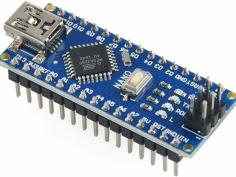
Arduino Nano Board R3 with CH340 chip Based on the Arduino platform, the Nano R3 Board CH340 Chip without USB Cable does all the functions of the Uno, but has a smaller footprint. Using Nano CH340 Soldered Board R3 Chip without USB cable is essential for your small project where you don’t need many pins, but the small size is very important to make it look nice. In comparison to older versions of Arduino Nano with FTDI USB-Serial Chip, the Nano uses a low-cost USB-Serial Chip. With the ATmega328 (Arduino Nano R3), the Nano is small, complete, and breadboard-friendly. It has more or less the same functionality as the Arduino Uno but in a different package. In addition to lacking a DC power jack, it uses a Mini-B USB cable instead of a standard one. This device can be powered by a mini-USB cable, a 6-20V unregulated external power supply (pin 30), or a 5V regulated external power supply (pin 27). Six PWM I/O are included from a total of 14 digital I/O, eight analog inputs, 16Mhz clock speed, and 32kB flash memory. Please note: The CH340 chip might not work directly with some PCs/laptops. You will need some drivers for the CH340 chip. Arduino nano features : TTL level serial transceiver ports (RX / TX) Atmel Atmega328P-AU MCU used It has a bootloader installed Supports USB download and power supply Provides support for external DC power supplies of 5V and 12V

Thumb

0 repins 0 comments

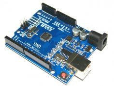
Arduino UNO SMD (CH340) Microcontroller Development Board Uno R3 CH340G ATmega328p Development Board is a low-cost version of the Uno R3. It uses a CH340 USB to Serial converter chip instead of an Atmega16U2. It has worked perfectly for us when we used a lot of low-cost Arduino boards with CH340 chips. This board works exactly like the more expensive version without the CH340 chip during normal operation. The CH340 chip is only used during programming and when using the serial output of the USB port. The following are the main changes from the previous version: This jumper has two rows of pin holes (male and female), so it can be connected to normal female jumpers. There are three additional rows of holes for wiring. The ATMEGA328P DIP package has been changed to a flat package. The CH340G replaces the ATmega16U2 Here’s how to use it: The Arduino IDE can be downloaded here The USB chip driver can be downloaded here The driver will be automatically installed when you plug in the UNO development board Choose the UNO from the die The COM port should be selected The best choice first, Arduino UNO SMD comes with routine procedures, burn them in. The Arduino Uno SMD CH340 microcontroller board is a compact yet powerful development platform that unleashes creativity in electronics and programming enthusiasts. The CH340 USB-to-serial chip ensures seamless connection with your computer while inheriting the legacy of the Arduino Uno. In conclusion: In summary, the Arduino Uno SMD CH340 microcontroller board combines the versatility of the Arduino platform with the convenience of surface-mount technology and CH340 connectivity. With this board, you can bring your electronic projects to life, whether you’re a student, educator, or professional. Get started with Arduino today, and unleash your creativity!

Thumb

0 repins 0 comments

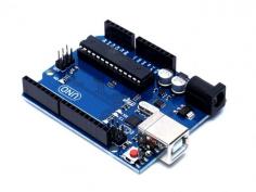
Arduino UNO R3 DIP with ATmega328P Are you looking to buy the Arduino Uno R3 CH340G ATMEGA328P Development Board for your next Arduino project? Don’t look any further! Ainow, your trusted electronic component supplier in India, offers you this exceptional development board, fully compatible with Arduino Uno R3 projects. In the world of electronics and programming, the Uno R3 CH340G ATMEGA328P Development Board is more than just a microcontroller board; it’s a gateway to endless possibilities. This board is engineered with precision and durability to meet the needs of both beginners and experienced enthusiasts. Its versatility knows no bounds – whether you’re into robotics, IoT, home automation, or creative automation projects, this board is perfect. Even new Arduino users will find it easy to use, thanks to the plug-and-play design and user-friendly interface. This development board’s ATmega328P microcontroller and CH340G USB-to-serial converter chip make sure seamless data transfer and efficient performance. You’ll be amazed at how fast your Arduino projects will run with this board. we believe in offering the best value for your investment. You can buy the Uno R3 CH340G ATMEGA328P Development Board for a competitive price, with no hidden charges. Our nationwide shipping ensures your order reaches you in perfect condition and in the fastest time possible. We detail Arduino code for making a smart dustbin, the required components, and the circuit diagram for making an automatic dustbin in our blog smart dustbin project using Arduino. For using this Uno R3 Board compatible with Arduino in your small or DIY projects, you will need some essential components, such as Breadboard Wire jumpers Power supply or batteries Motors made by BO Drivers of motor vehicles The sensors Check out the Arduino Uno R3 compatible board

Thumb

0 repins 0 comments